
 Business License

Mining Big Gear Basics: How a Large Girth Gear Drives a Grinding Mill
A grinding mill turns because its ring gear turns with it.
That ring, bolted around the shell, collects the torque produced by the motor, the reducer, and the pinion, and hands it to the mill body.
When the mesh sits correctly, the drive runs quietly and the flanks wear evenly across the face.
When it does not, a tooth problem can stop a mill whose bearings, liners, and shell are all in sound condition.
This article explains what a mining big gear does in a grinding drive, where a large girth gear sits in the drive train, and which parts make up a mill girth gear assembly.
It also covers the tooth geometry, the alignment figures, and the lubrication routine that keep the mesh healthy.
The closing section lists the damage modes that decide when the ring has to come off the shell.
1. What a Mining Big Gear Does in a Grinding Drive
A mining big gear is the large toothed ring that carries the drive torque of a grinding mill into the mill shell.
It is the biggest single component in the drive train and often the heaviest item on the machine, with rings for large mills weighing anywhere from roughly 20 to 120 tonnes.
Its job is simple to state and demanding to execute: take a fast, low-torque input from a small pinion and convert it into a slow, high-torque rotation of the shell.
That conversion happens across one mesh.
A pinion with roughly 18 to 26 teeth drives a ring with 180 to 260 teeth, giving a single-stage ratio in the region of 8 to 12 to one.
The ring therefore sits between the gearbox and the shell, at the point where the last and largest step of the speed reduction takes place.
Because the ring is bolted directly to the shell flange, every measurement taken on it describes the condition of the whole rotating assembly.
Radial runout, axial runout, and tooth wear report on the shell, the flange, and the foundation at the same time.
This is why a mining big gear is treated as a condition indicator and not merely as a part that wears out.
2. Where a Large Girth Gear Sits in the Drive Train
A large girth gear occupies the last position in a chain that starts at the motor terminals.
Power travels from the motor through a coupling into a reducer, out of the reducer into the pinion shaft, across the mesh into the ring, and from the ring through the shell flange into the mill body.
Every element in that chain loses a little energy, and the mesh is where those losses show up most clearly as heat and noise.
Large mills often use two pinions rather than one.
A dual-pinion arrangement places the pinions roughly 180 degrees apart around the ring, which halves the tangential load on each mesh and lets the same large girth gear carry a heavier mill power.
The two drives have to share load evenly, and that share is checked by comparing motor current rather than by looking at the teeth.
Some very large mills remove the ring drive altogether and use a ring motor wrapped around the shell.
That arrangement has no girth gear, no pinion, and no reducer, and it costs more to build and more to service when a winding fails.
Most grinding circuits in service still rely on a large girth gear and pinion, which is why the mesh stays at the centre of maintenance planning.
3. Parts Inside a Mill Girth Gear Assembly
A mill girth gear assembly is more than the toothed ring.
It includes the ring segments, the joint hardware that holds them together, the bolted connection to the shell flange, the pinion and its shaft, the bearings, and the lubrication hardware that feeds the mesh.
Buyers who order a replacement ring sometimes forget the joint hardware and the spray nozzles, and then lose a maintenance window waiting for parts that weigh a few kilograms.
The table groups the main items by function and gives the figure that matters for each.
| Part group | Typical items | Function | Figure to watch |
|---|---|---|---|
| Ring segments | cast or forged ring in 2 or 4 pieces | carry the drive torque | segment joint fit |
| Joint hardware | fitted bolts, dowel pins, shrink links | hold the segments in register | joint gap, bolt stretch |
| Shell connection | flange bolts, keys, support pads | pass torque into the shell | radial runout |
| Pinion set | pinion, shaft, key | introduce torque to the mesh | flank wear, pinion runout |
| Bearings | pinion bearing, housing | hold the pinion in position | clearance, oil film |
| Lubrication | spray nozzle, pump, filter | build a film on the flank | spray pattern, film thickness |
The assembly works as a system, and a shortfall in one part shows up as damage in another.
A loose joint between two ring halves, for instance, changes the tooth spacing at the joint and overloads the teeth on either side of it.
Shenyang Delonshine Technology quotes these items as one package for that reason, so the joint hardware and the spray nozzles arrive with the ring rather than after it.
4. How a Mining Big Gear Carries Torque from Motor to Shell
Torque figures explain why a mining big gear is built the way it is.
A mill drawing 10 megawatts at 13 revolutions per minute needs a shaft torque of roughly 7.3 meganewton metres, and a ring with a pitch diameter of 10 metres converts that into a tangential force of about 1.5 meganewton across the mesh.
That force is shared across several teeth at any moment, which is why the contact pattern matters more than any single tooth measurement.
The force also explains the choice of face width.
Rings for large mills typically run a face width between roughly 600 and 1,000 millimetres, so the load spreads along a line instead of concentrating at a point.
If the pinion sits out of alignment, that line shortens to one end of the face and the local stress rises sharply.
Helical teeth respond to the same load by entering the mesh gradually rather than meeting the full face at once, at the cost of an axial thrust that the bearing arrangement has to absorb.
5. Tooth Form and Module on a Large Girth Gear
Module sets the size of the tooth, and on a large girth gear it is a large number.
Grinding mill rings commonly run modules between roughly 22 and 40 millimetres, with a pressure angle of 20 degrees or 25 degrees and full-depth involute flanks.
Module and pressure angle are fixed by the drive design, so a replacement ring has to match both figures before any other question is discussed.
Backlash is the clearance between the flanks of a meshing pair, and it has to be there.
Too little backlash traps lubricant and heat in the mesh, while too much lets the teeth hammer each other on every reversal of load.
On a ring of this size a working figure usually sits between roughly 0.6 and 1.5 millimetres at the pitch circle, adjusted for the operating temperature of the drive.
The table sets out the tooth parameters that belong on a replacement enquiry.
| Parameter | Typical range | Why it matters |
|---|---|---|
| Module | 22 to 40 mm | sets tooth size and must match the drawing |
| Pressure angle | 20 or 25 degrees | fixes the direction of load on the flank |
| Helix angle | 5 to 15 degrees | smooths tooth entry and reduces impact |
| Face width | 600 to 1,000 mm | spreads the tangential load |
| Backlash | 0.6 to 1.5 mm | leaves room for lubricant and expansion |
| Flank hardness | 300 to 350 HB | resists pitting and slow wear |
Tooth hardness is applied after machining rather than through the full section.
Induction or flame hardening produces a hard case on the flank while the core stays tough enough to carry the bending load at the root.
A ring with the right hardness but the wrong case depth may look correct on a certificate and still fail early in service.
6. Alignment and Backlash in a Mill Girth Gear Assembly
Alignment work on a mill girth gear assembly is measured, recorded, and then repeated, because the figures move as the mill heats up.
Radial runout of the ring against the shell is normally held within roughly 0.5 to 1.5 millimetres, and axial runout inside a similar band, depending on ring diameter.
Both figures are taken with a dial indicator mounted on a fixed frame while the mill is barred over slowly.
Pinion alignment is checked in the same session.
The pinion axis has to sit parallel to the ring axis in both planes, and the tooth contact pattern is read with marking compound on several teeth around the ring.
A pattern that sits at one end of the face in one position and at the other end opposite it points to an alignment error rather than a gear fault.
Cold and hot readings both matter, because a mill aligned cold can move out of tolerance once the shell reaches operating temperature.
The usual practice is to record both sets and to set the cold alignment so that the hot figures land inside the band.
Owners who skip the hot reading often find the same tooth damage returning after every rebuild of the assembly.
7. Lubrication Practice for a Mining Big Gear
Open gear lubrication has one purpose: keep a film of lubricant between the flanks so that metal never touches metal.
Spray systems deliver a measured quantity of heavy open gear lubricant to the meshing side of the teeth at a set interval.
The interval and the quantity are set by the drive supplier and should be treated as settings rather than suggestions.
The lubricant also has to stay on the flank.
Products intended for a mining big gear use a base oil of high viscosity together with an additive package that gives the film enough cohesion to survive the contact pressure at the pitch line.
Spraying too much wastes lubricant and throws material off the ring, while spraying too little lets the flanks polish and then pit.
Temperature belongs in the same record as the lubricant.
A healthy mesh runs with a flank temperature below roughly 65 degrees Celsius, and a rising trend at constant load usually means the film is failing rather than the ambient temperature climbing.
Particle contamination is the second signal to watch, because grit carried into the mesh turns a lubricant problem into a wear problem quickly.
Delonshine Technology issues a spray setting sheet with each ring, so the lubricant routine is carried over with the part instead of being worked out again on site.
8. Damage Modes That End the Life of a Large Girth Gear
Damage on a large girth gear falls into a small number of recognisable groups.
Deciding which group applies determines whether the ring can stay in service, whether it can be re-profiled, or whether it has to be replaced.
The table lists the groups, their usual cause, and the response each one calls for.
| Mode | Appearance | Usual cause | Response |
|---|---|---|---|
| Pitting | small craters on the flank | thin lubricant film, overload | monitor area, dress if early |
| Spalling | large flakes of case lost | subsurface defect or shallow case | schedule replacement |
| Scoring | axial scratches along the flank | contamination in the lubricant | clean, filter, re-inspect |
| Root crack | crack at the tooth fillet | bending fatigue, misalignment | magnetic particle test, replace |
| Rim crack | crack across the rim section | casting defect or thermal stress | ultrasonic test, replace |
| Joint fretting | wear at the segment joint | loose joint hardware | re-torque, re-fit pins |
| Hole elongation | oval holes at the shell flange | torque loss and movement | ream and fit larger bolts |
The pattern of the damage is as useful as its type.
Wear concentrated at one end of the face points to alignment, while wear spread evenly across all teeth points to lubricant or load.
A single damaged tooth surrounded by healthy ones usually means a hard object passed through the mesh rather than a systemic problem.
Shenyang Delonshine Technology reviews flank photographs and runout records before quoting a replacement ring, because the two together show whether the fault sits in the gear or in the drive.
Delonshine Technology also keeps module and pressure angle on file so a replacement can be produced against the drawing the mill was built to.
9. Mining Big Gear: Questions Buyers Ask
These are the questions that come up most often when a plant is preparing to order a ring.
9.1 How long does a mining big gear last?
Service life depends far more on the maintenance routine than on the calendar. A ring that is aligned correctly and lubricated on schedule in a well-run circuit can stay in service for many years before the flanks reach their wear limit, while the same ring in a circuit with a failing lubricant film can pit within a few campaigns. The useful measure is flank wear and contact pattern at each major mill stop, not an expected number of years. Records taken at the same position over several stops turn that into a trend, and the trend decides the order date.
9.2 What is the difference between a girth gear and a pinion?
The girth gear is the large ring bolted to the mill shell, and the pinion is the much smaller gear that drives it. The pinion turns several times for each single turn of the ring, which is how the drive achieves its speed reduction, and the pinion is also the cheaper and faster item to replace. Because the pinion makes many more revolutions, it wears faster in absolute terms, and most plants keep a spare pinion in stock while treating the ring as a long-life part. The pair has to be specified together, since module and pressure angle are shared between them.
9.3 Can a mill girth gear assembly be repaired in place?
Some repairs are possible with the ring still on the shell, and joint hardware can be replaced without removing it at all. Flank damage that has not reached the root can be dressed with a hand grinder or a specialist tool, and bolt hole elongation can be corrected by reaming and fitting oversized bolts. Damage that reaches the tooth root, or a crack in the rim section, cannot be repaired in place and has to be assessed by ultrasonic and magnetic particle testing before any decision is made. A mill girth gear assembly in that condition normally calls for a replacement ring and a planned outage.
9.4 What information is needed to quote a replacement mining big gear?
A quotation needs the module, pressure angle, helix angle, number of teeth, face width, outside diameter, and the bolt pattern on the shell flange. The original drawing and any dimensional record taken from the installed ring will support those figures. Material grade, required flank hardness, and the inspection documents expected on delivery should be stated at the same time. A supplier who receives this package can quote without assumptions, and the buyer avoids the risk of a ring that arrives with the correct diameter and the wrong tooth form.
Recently Posted
-
Cast or Forged: Choosing the Material for a Mining Big Gear
September 24, 2026Two mills of similar size can carry rings made by two different processes, and neither owner is making a mistake. A cast steel big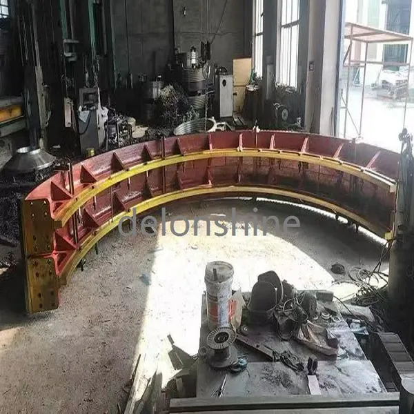 Read More
 -
Repair and Refurbishment of Large Mining Equipment End Covers
September 24, 2026A large end cover can weigh several tonnes and cost as much as a small machine, so the decision to replace one deserves more thoug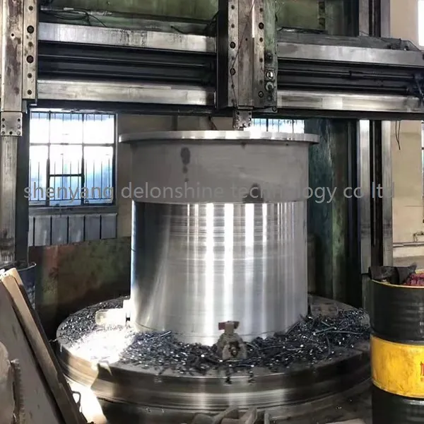 Read More
 -
Lead Time Planning for Jaw Crusher Toggle Plates
September 23, 2026A toggle plate is a small casting against the weight of a jaw crusher, and that is exactly why it is easy to leave out of the purc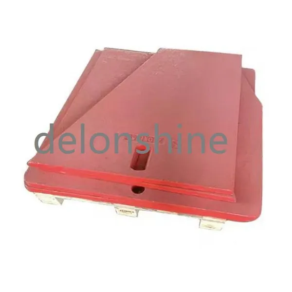 Read More
 -
Mining Equipment End Covers for Mobile and Semi-Mobile Plants
September 23, 2026A mobile crushing plant moves, and every heavy casting inside it has to survive that movement as well as the duty it was designed
Read More

Contact Us
Recommended Products
-
 Vertical Mill Reducer Planetary Gear AssemblyNegotiableMOQ: 2 Combos
 -
High Precision Mining Equipment End Cover Wear Resistant Crusher End CapNegotiableMOQ: 2 Pieces
-
Heavy Duty Mining Equipment Cast HousingNegotiableMOQ: 2 Pieces
-
Mining Parts Concave MantleNegotiableMOQ: 2 Pieces
-
High Strength Cast Steel Crusher Lifting Beam Heavy Load Mining Equipment Spare PartNegotiableMOQ: 2 Pieces
-
OEM Replacement Mining Spare Parts for Stone Crushing PlantNegotiableMOQ: 2 Pieces
-
Cast Steel Ball Mill Head for Mineral ProcessingNegotiableMOQ: 2 Pieces
-
Large Diameter Cast Gear for Ore Grinding MillNegotiableMOQ: 2 Pieces
-
Wear Resistant Mining Spare PartsNegotiableMOQ: 2 Pieces
-
Industrial Wet Dry Ball Mill for Mineral ProcessingNegotiableMOQ: 2 Pieces


-
High Wear Resistant Ball Mill Wear Parts Ball Mill Gear Pinion Liner for Mining Processing PlantNegotiableMOQ: 2 Pieces
-
Heavy Duty Equipment CasingNegotiableMOQ: 2 Pieces
-
Customized Main Shaft for Cone CrusherNegotiableMOQ: 2 Pieces
-
Ball Mill Head With Flange and Bolt HolesNegotiableMOQ: 2 Pieces
-
Heavy Duty Equipment CasingNegotiableMOQ: 2 Pieces


-
Crusher Wear Parts for Mining MachineryNegotiableMOQ: 2 Pieces
-
High Manganese Steel Jaw Crusher Fixed & Swing PlatesNegotiableMOQ: 2 Pieces
-
Cast Steel Safety Toggle Plate for Jaw Crusher Overload ProtectionNegotiableMOQ: 2 Pieces
-
High Manganese Steel Mill LinerNegotiableMOQ: 2 Pieces
-
Main Shaft Steel Sleeve Lock Nut for Cone CrusherNegotiableMOQ: 2 Pieces