
 Business License

Feed Hoppers at Primary Crushing Stations
A primary crushing station hopper is the least technical item in the circuit and the one that stops production most often, because it is the first part to touch the rock in the condition it arrives from the pit.
At a copper operation the hopper walls were relined with 12 millimetre plates where the original drawing called for 20 millimetres, on the reasoning that the plates would be replaced sooner at a lower unit cost.
The wall holed out in about five months, on a wet shift the material ran through the opening onto the floor, and the station stood while the wall was cut out and rebuilt.
This article looks at what a mine feed hopper has to do at a primary station, where a run of mine hopper liner wears, and how the walls, the opening and the discharge area are planned as one system.
1. What a Primary Crushing Station Hopper Has to Do
A primary crushing station hopper receives rock delivered by truck, shovel or conveyor and holds it long enough to feed the crusher at a steady rate.
It is a buffer, an interface and a wear item at the same time, and those three roles pull the design in different directions.
As a buffer it has to hold enough material to keep the crusher loaded while a truck turns or a shovel repositions.
As an interface it has to accept a discharge that arrives in surges and deliver a flow that a feeder can control.
And as a wear item it has to survive impact from the drop and abrasion from material sliding down the walls.
Primary crushing station hopper design starts from the delivery method rather than from the crusher.
A truck dumping a 90 tonne payload into the opening delivers a concentrated impact on the floor and the back wall.
A shovel loading continuously spreads the same tonnage over a wider area but keeps the walls under constant abrasion.
A conveyor feeding the station removes the impact but adds a transfer point that wears its own way through the structure.
2. Feed Size and the Mine Feed Hopper Opening
The opening of a mine feed hopper is sized from the largest lump the pit will deliver, and getting that figure wrong is the most expensive mistake in the station.
A rule of thumb places the opening at roughly two and a half to three times the top size of the feed, so a 1,000 millimetre lump needs an opening around 2,500 to 3,000 millimetres.
A tighter opening saves steel and forces operators to break oversize on the lip, which is a slow and hazardous job.
A wider opening costs more steel and passes a lump that the crusher cannot swallow, so the oversize goes through the chamber and damages the liners.
Three dimensions describe the opening on most drawings.
The gape, which is the width between the two long walls.
The length, which runs along the feeder or the crusher axis.
And the height of the lip above the floor, which sets how much rock stands against the wall when the hopper is full.
Feed size also decides the admission path into the station.
Where a truck dumps directly into the hopper, the lip needs a rock box or a lined face to take the impact.
Where a grizzly sits over the opening, the bar spacing is set from the crusher feed opening rather than from the truck.
3. Buffer Capacity and the Run of Mine Hopper Liner
Buffer capacity is the figure that decides how much of the run of mine hopper liner is in contact with material during a normal shift.
A hopper that is kept nearly empty wears its floor and lower walls with every load, because every tonne slides over the same plate.
A hopper kept above a working level forms a static bed of rock, and material then slides over rock rather than over steel.
That bed is the most economical wear protection available at a primary station, and it costs nothing beyond the discipline to keep the level up.
The figures below show how the level in the hopper changes the wear picture.
A hopper of 250 tonnes live capacity fed by 90 tonne trucks stands about three loads deep when full.
Held at half capacity, the walls see sliding contact from roughly half the annual tonnage.
Held above two thirds capacity, most of the sliding happens within the material itself.
A run of mine hopper liner still has to be designed for the times when the level is low, which is why plate selection cannot be based on the ideal operating condition.
4. Run of Mine Hopper Liner Zones and Plate Selection
A run of mine hopper liner is not one plate specification across the whole shell, because the zones do different work.
The table below sets out the zones that appear on most primary station drawings and the duty each one carries.
| Zone | Dominant wear | Typical plate |
|---|---|---|
| Impact face under the dump | heavy impact plus abrasion | 20 to 40 millimetre plate or a rock box |
| Upper back wall | sliding abrasion | 12 to 20 millimetre plate |
| Lower walls and throat | sliding abrasion at high pressure | 16 to 25 millimetre plate or a harder grade |
| Floor and discharge lip | abrasion with some impact | 20 to 30 millimetre plate |
| Grizzly bars | impact and bending | 40 to 80 millimetre section or cast bars |
Plate thickness is half the decision, because the grade matters as much as the section.
An abrasion resistant plate of moderate thickness can outlast a mild steel plate twice as thick in a sliding wear zone.
In an impact zone the harder plate may crack instead of deforming, so a tougher grade in a heavier section is the safer specification.
Shenyang Delonshine Technology supplies liner plate and cast wear blocks for hopper work, and it asks which zone a plate is going into before proposing a grade.
5. Grizzlies and the Mine Feed Hopper Discharge
The discharge area of a mine feed hopper is where the flow is controlled, and a grizzly over the opening is often the first control in the station.
Bars set at the right spacing scalp the fines before they reach the crusher, which raises crusher capacity and reduces the volume of material that has to be crushed.
The spacing follows the crusher setting rather than the truck, so fines passing through the bars bypass the chamber entirely.
On some stations the grizzly is fixed, and on others it is a vibrating unit that also acts as the feeder.
The grizzly has its own wear pattern.
Bars wear at the top edge where rock lands and at the sides where material slides along them.
Cast bars with a thickened section at the impact point outlast plain plate bars, and they can be turned or rotated before they are replaced.
A grizzly that has worn to an open spacing passes oversize into the crusher, which then shows up as a rapid loss of liner section in the chamber.
Where a feeder sits under the hopper, the interface between the two is a wear point in its own right.
A pan feeder receives the full weight of the column above it, so the pan, the chain and the skirt rubbers are all part of the station wear budget.
6. Primary Crushing Station Hopper Walls and Discharge Angle
The wall angle on a primary crushing station hopper decides whether material flows or hangs, and the angle has to suit the rock rather than the available space.
Dry, blocky rock flows on a steep wall, while wet or clay bearing material needs a steeper angle and a smoother surface to move at all.
As a working figure, walls are commonly set between 55 and 70 degrees from the horizontal, with the steeper end used for sticky material.
Three practical limits shape the wall design.
A wall that is too shallow holds a dead zone of material that never moves, and that zone grows until the live capacity falls below what the feeder needs.
A wall lined with thick plates reduces the effective angle, because the plate face sits inside the original steel line.
And a wall with a ledge or a step gives material somewhere to sit, which turns a small hold up into a full blockage.
The discharge throat matters as much as the walls.
A throat that narrows too quickly creates an arch of material above it, and an arch stops the station as completely as a plugged crusher.
The throat width is normally set at two to three times the largest lump in the feed, in the same way as the opening above it.
Shenyang Delonshine Technology Co Ltd reviews wall angles and throat widths against the rock type a customer is actually running, rather than against a standard drawing.
7. Bridging and Plugging in a Mine Feed Hopper
Bridging and plugging are the two failure modes that stop a primary station, and they are different problems with different causes.
A bridge forms when lumps lock together across an opening and hold the column above them.
A plug forms when fine wet material packs into the throat and refuses to move even when the arch above it is broken.
Four causes cover most incidents.
Moisture in the feed, which makes fines sticky and raises the internal friction of the mass.
A throat or grizzly spacing that is too tight for the material being delivered.
A worn plate face that has developed a lip, so material catches on the step.
And a discharge rate that is held back while trucks keep tipping, so the level rises above the design depth.
Clearing a blockage is the most dangerous routine task at a primary station, because a column of rock can release without warning.
The safe approach is to stop the feed, work from a platform, and use a mechanical breaker or a hopper vibrator rather than standing on the material.
A wet season plan is worth writing in advance, since the same material that flows in dry weather will bridge after two days of rain.
8. Repair Planning for a Run of Mine Hopper Liner
Repair planning for a run of mine hopper liner is normally done from inspection records rather than from a calendar, because the wear rate changes with the level kept in the hopper.
A wall measured at six month intervals builds a picture of where the section is going, and that picture tells a planner which zone to order first.
An inspection worth the name covers five points.
Plate thickness at marked points on the impact face, the back wall and the throat.
The condition of the lip and the floor around the discharge.
Any build up of packed material in a corner or on a ledge.
The condition of the structure behind the plates, since a wall that has been holed will have corroded or abraded the parent steel as well.
And the state of the grizzly bars, including the spacing measured between them.
A staged repair keeps the station working while the liner is renewed.
The impact face and the throat are usually repaired first, because a hole in either one puts material on the floor.
Upper walls can follow in the next scheduled stop once the plates are on site and the structure has been checked.
Delonshine supplies hopper liner plate cut to drawing, and a customer who keeps a set of the two worst zones in stock can cut a hopper repair from days to hours.
Delonshine Technology works from photographs and dimensions where no drawing exists, which is common on stations that have been modified more than once since they were built.
9. Frequently Asked Questions about the Primary Crushing Station Hopper
9.1 How is the opening of a primary crushing station hopper sized?
The opening follows the largest lump the pit will deliver, and a common working figure places it at two and a half to three times that dimension. A 1,000 millimetre lump therefore calls for an opening around 2,500 to 3,000 millimetres. A tighter opening forces operators to break oversize on the lip, which is slow and hazardous, while a wider opening lets a lump through that the crusher cannot take. The lip height and the feeder width are then set from the dumping method.
9.2 How thick should a mine feed hopper liner be?
Thickness follows the zone rather than the whole shell. An impact face under a direct truck dump is usually 20 to 40 millimetres thick or protected by a rock box, sliding upper walls run 12 to 20 millimetres, and floors and throats sit between 16 and 30 millimetres. Grade matters as much as section, because an abrasion resistant plate can outlast mild steel of twice the thickness in a sliding zone, while a tough grade in a heavier section is safer where impact dominates. The lip face and the throat are normally specified a step thicker than the walls above them.
9.3 Why does a run of mine hopper liner wear faster than expected?
A liner often wears faster than the design assumed because the hopper is run at a low level, so every tonne slides across the plate instead of across a static bed of rock. Wet feed raises the friction and the sliding pressure, and a ledge or a worn plate lip gives material somewhere to catch and concentrate the wear. Keeping a working level in the hopper is the most economical control available, because it puts rock against rock in place of steel.
9.4 What can be done about bridging and plugging in a mine feed hopper?
Bridging and plugging are managed by design and by feed control rather than by clearing blockages. A throat at two to three times the largest lump, walls between 55 and 70 degrees, and a smooth plate face with no ledges all reduce the chance of an arch forming. For sticky material, a steeper wall and a hopper vibrator help, and a wet season plan that changes the feed blend before the rain arrives prevents more blockages than any tool used after one has formed.
Recently Posted
-
From Sample to Delivery: Our Workflow for Wear Parts Projects
November 4, 2026A wear parts project workflow decides whether a replacement part simply arrives or whether it arrives at the right time, in the ri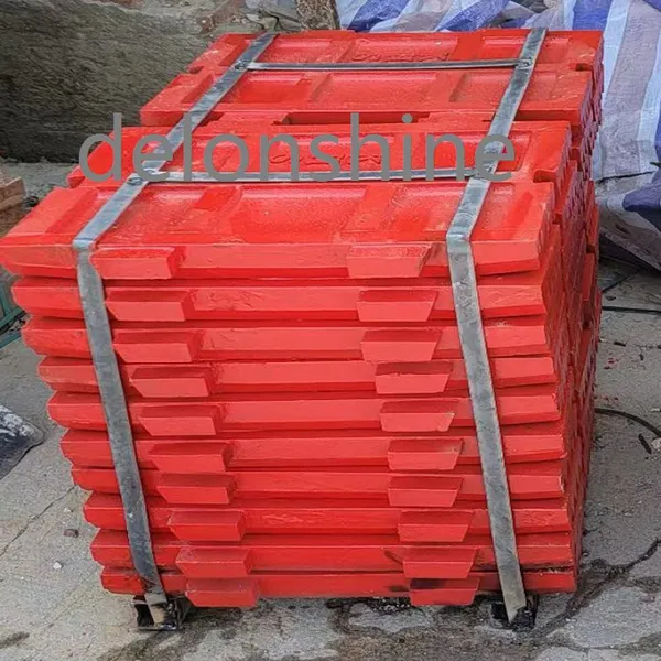 Read More
-
Serving Cone and Jaw Crusher Plants Across Our Export Regions
November 4, 2026Our crusher parts export regions now cover thirteen markets, and each one asks for something slightly different from a wear parts Read More
-
Custom Wear Plate Fabrication for Hoppers and Chutes
November 3, 2026Custom wear plate fabrication starts from a drawing of the wall the plate has to cover rather than from a catalogue of standard si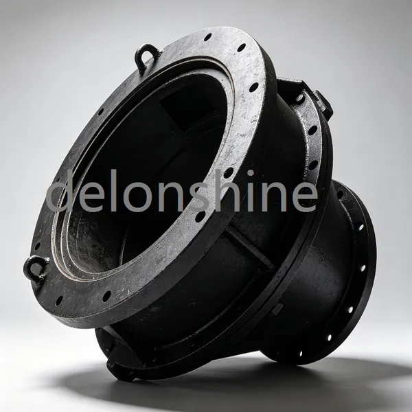 Read More
-
Machining Capability for Large Nuts, Sleeves and Hubs
November 3, 2026A foundry that casts a sleeve lock nut and cannot machine it has delivered half a part, and this article is about the other half.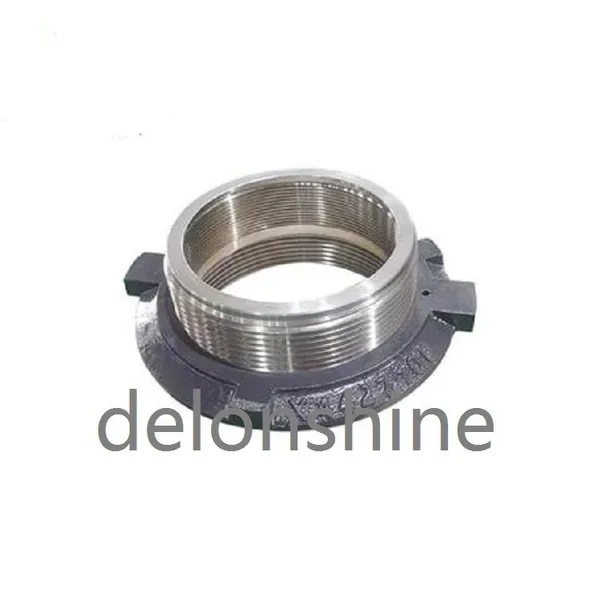 Read More

Contact Us
Recommended Products
-
 Vertical Mill Reducer Planetary Gear AssemblyNegotiableMOQ: 2 Combos
-
Heavy Duty Mining Equipment Cast HousingNegotiableMOQ: 2 Pieces
-
High Strength Cast Steel Crusher Lifting Beam Heavy Load Mining Equipment Spare PartNegotiableMOQ: 2 Pieces
-
OEM Replacement Mining Spare Parts for Stone Crushing PlantNegotiableMOQ: 2 Pieces
-
Cast Steel Ball Mill Head for Mineral ProcessingNegotiableMOQ: 2 Pieces
-
Large Diameter Cast Gear for Ore Grinding MillNegotiableMOQ: 2 Pieces
-
Wear Resistant Mining Spare PartsNegotiableMOQ: 2 Pieces
-
Industrial Wet Dry Ball Mill for Mineral ProcessingNegotiableMOQ: 2 Pieces
-
High Wear Resistant Ball Mill Wear Parts Ball Mill Gear Pinion Liner for Mining Processing PlantNegotiableMOQ: 2 Pieces
-
Customized Main Shaft for Cone CrusherNegotiableMOQ: 2 Pieces



-
Ball Mill Head With Flange and Bolt HolesNegotiableMOQ: 2 Pieces
-
Heavy Duty Equipment CasingNegotiableMOQ: 2 Pieces
-
Crusher Wear Parts for Mining MachineryNegotiableMOQ: 2 Pieces
-
High Manganese Steel Jaw Crusher Fixed & Swing PlatesNegotiableMOQ: 2 Pieces
-
Cast Steel Safety Toggle Plate for Jaw Crusher Overload ProtectionUS$ 10 - 15MOQ: 10 Pieces


-
Main Shaft Steel Sleeve Lock Nut for Cone CrusherUS$ 318 - 350MOQ: 1 Piece
-
High Manganese Steel OEM Cone Crusher Bowl Liner According to DrawingsUS$ 800 - 850MOQ: 1 Piece
-
High Precision Mining Equipment End Cover Wear Resistant Crusher End CapUS$ 25000 - 26000MOQ: 1 Piece
-
High Manganese Strong Wear and Impact Resistance Steel Alloy RollUS$ 10 - 15MOQ: 1 Piece
-
High Alloy Cast Hammer Head Great Wear & Impact ResistanceUS$ 10 - 15MOQ: 1 Piece