
 Business License

Ultrasonic and Magnetic Particle Testing on Mining Big Gears
A mining big gear weighing 20 tonnes and measuring 5 metres across cannot be inspected by looking at it.
The defects that end its life early are inside the casting or sitting just below a tooth flank, invisible from the surface and expensive to discover after the ring has been fitted to a mill.
Two nondestructive methods carry most of that burden in a heavy casting works.
This article explains what big gear ultrasonic testing finds, what a magnetic particle inspection gear check adds, and how a buyer can tell whether the reports behind a shipment are worth the paper they are printed on.
1. Why Nondestructive Testing Matters for a Large Mining Big Gear
A mining big gear is one of the largest single-piece castings a foundry produces.
Rings for large mills typically fall between 3 and 8 metres in diameter and between 8 and 40 tonnes in finished weight, and a single ring can serve a mill for a decade or more.
That combination of size, cost and service length is why inspection is planned rather than optional.
The consequences of a defect are asymmetric.
A casting fault found at the works costs a repair pass, a re-test and a few days of schedule.
The same fault found after installation costs a mill outage measured in weeks, plus freight and crane work at both ends of the journey.
Inspection exists to move the discovery point upstream.
Casting defects also behave differently in service from what a static inspection might suggest.
A small internal void in a low-stress region may never grow, while a similar void beneath a tooth root becomes a fatigue crack origin under a cyclic load.
Location therefore matters as much as size, which is one reason a defect report has to record position rather than a single dimension.
2. Ultrasonic Testing of a Big Gear: What the Method Finds
Ultrasonic testing sends a high frequency pulse into the material and reads the echoes that return.
On a large ring it is used mainly to detect internal discontinuities: shrinkage cavities, slag inclusions, gas porosity and internal cracks.
Frequencies between roughly 1 and 5 MHz are typical, with the lower end used for thick sections and coarse grain structures.
In big gear ultrasonic testing, coverage is the first question a buyer should ask about.
A ring is examined on the rim face, on the web or bore where the geometry allows, and from the tooth flank surface.
The recorded figure should be a percentage of the accessible volume rather than a general statement that testing was carried out.
Grain structure sets a practical limit.
Large cast steel sections scatter ultrasound, and the resulting grass on the display masks small defects in some regions.
A competent report states where the method became unreliable instead of presenting a uniform picture of full coverage.
A buyer reviewing big gear ultrasonic testing results should read that statement as a limitation of the technique rather than as a shortcoming of the works.
Reference blocks support the calibration.
A block with known flat-bottomed holes of several diameters establishes the sensitivity, and the resulting distance amplitude curve gives the examiner something to compare against.
Without it, a reported defect size is an opinion rather than a measurement.
3. Reading a Big Gear Ultrasonic Testing Report
A report from a big gear ultrasonic testing exercise should be readable by an engineer who was not present.
That means it should record the technique, the equipment, the calibration and the results in a form that can be checked later.
Reports that list a pass verdict and nothing else are of little use in a warranty discussion.
Six items belong in every report.
The probe type and frequency, the reference block and calibration figures, the surfaces examined, the scanning coverage achieved, the position and size of every indication above the recording threshold, and the disposition of each one.
Recording threshold deserves particular attention, because a threshold set high enough hides most small indications from the record without changing the verdict.
Position is recorded in a coordinate system the ring itself defines.
Tooth number, distance from the reference face and depth below the surface are the usual three values.
That makes it possible to find the same indication again on a later inspection and to compare size over time.
The report should also state the acceptance standard applied.
ASTM and EN practice both define severity levels by defect type and location, and a report that quotes a standard without naming the level leaves the buyer guessing.
Delonshine attaches the calibration record to the same document, so a reviewer can check the sensitivity at which the figures were taken.
4. Magnetic Particle Inspection on Gear Teeth and Root Radii
Magnetic particle inspection finds defects that reach or nearly reach the surface.
On a gear ring it is applied mainly to the machined tooth flanks, the root radii and the joint faces.
The root radius is the critical region, because it is where the bending stress concentrates on every revolution.
The technique magnetises the area and applies a fine ferromagnetic powder, which collects at any discontinuity and forms a visible indication.
Wet fluorescent methods under ultraviolet light are commonly used on large parts because they show fine indications that dry powder would miss.
Alternating current magnetisation concentrates the field near the surface, while direct current or half-wave rectified current reaches deeper.
A magnetic particle inspection gear check reports surface and near-surface defects rather than internal ones.
Its strength is sensitivity to cracks that are too tight and too shallow for the eye, and its limit is depth.
Reading a report from this method therefore requires knowing which faces were magnetised and in which direction.
Direction matters because a magnetic field finds defects running across it.
A tooth flank examined in a single direction leaves cracks running parallel to that direction undetected.
Two directions at roughly right angles is normal practice for a magnetic particle inspection gear check on a finished tooth form.
5. Where a Magnetic Particle Inspection Gear Check Belongs in the Process
Timing decides how much a gear casting defect check is worth.
Applied at the wrong stage, the same technique produces sound results that arrive too late to change anything.
Three points in the manufacturing route are worth planning.
The first is after rough machining, when the tooth form exists but material remains for correction.
An indication found at that stage can be removed by further machining or dressed by local grinding, and the casting continues through the route.
The second is after final machining and before despatch, which is the point that protects the buyer rather than the works.
A gear casting defect check at that stage can be closed by machining rather than by a concession.
The third sits after any weld repair.
A repaired area is re-inspected with the same technique and the same acceptance criteria as the original surface.
A report that covers the original casting but not the repair has a gap in exactly the place where a defect is most likely.
6. Casting Defects and the Gear Casting Defect Check
A gear casting defect check starts from the defects that large steel castings actually produce.
Knowing the likely type guides the choice of method, the regions to scan and the acceptance criteria to apply.
The table below summarises the main types and how they are found.
| Defect type | Where it occurs | Detection method |
|---|---|---|
| Shrinkage cavity | thick sections, rim to web junctions | ultrasonic testing |
| Gas porosity | dispersed through heavy sections | ultrasonic testing |
| Slag inclusion | random within the casting | ultrasonic testing |
| Hot tear | changes of section | magnetic particle and visual |
| Grinding crack | machined tooth flanks | magnetic particle inspection |
| Weld repair defect | repaired regions | both methods after repair |
Shrinkage is the most common internal defect in a heavy ring.
It forms where a thick section feeds a thinner one and the last liquid solidifies without enough metal to fill the space.
Riser design and chilling practice are the foundry controls, and ultrasonic testing is how the result is verified.
Grinding cracks are a machining artifact rather than a casting fault, and they appear when a tooth flank is ground with too much heat or too little coolant.
A magnetic particle inspection gear check after final grinding is the routine control against them.
Delonshine Technology records the heat number and the inspection result for every ring on one file, so the two can be matched without a search through paperwork.
7. Accept and Reject Criteria for a Gear Casting
Acceptance criteria turn an inspection result into a decision, and they should be agreed before the casting is poured.
Two variables drive most of the judgement: the type of indication and its location relative to the working surfaces.
A gear casting defect check is worth no more than the criteria written against it.
Shenyang Delonshine Technology agrees the criteria with the buyer before pouring, so the judgement is a written one rather than a held opinion.
Location is expressed as critical and non-critical regions.
The tooth flanks, root radii and the rim volume directly beneath the teeth are critical, because a defect there is loaded on every revolution.
The same indication in a low-stress web region may be acceptable at a larger size.
Size limits are normally written as a maximum dimension for a single indication and a maximum number or total area within a defined reference volume.
A clause allowing scattered indications below a stated size is a design decision, not a concession.
What is not acceptable is a criterion that leaves the judgement to the inspector without a written basis.
Repair policy belongs in the same document.
Excavation and welding of a defect is permitted within stated limits, followed by re-inspection with the original method.
The buyer should know from the report how much of the casting was repaired, because a heavily repaired ring behaves differently from a clean one in a fatigue assessment.
8. Combining Ultrasonic and Magnetic Particle Results on One Gear
The two methods answer different questions, and a complete file needs both.
Big gear ultrasonic testing covers the interior and misses surface-breaking defects that lie parallel to the beam.
Magnetic particle inspection covers the surface and near surface and cannot see anything deep inside a rim section.
A European mill operator bought a replacement ring for a large grinding mill, and the file supplied with the shipment contained a dimensional report and a single line stating that testing had been carried out.
A second ring from the same supplier arrived later with a full inspection file covering both methods, and comparing the two documents showed how much the first had left unsaid.
The plant now writes the report contents into the purchase specification rather than leaving the format to the supplier.
A second case involved a repair region on a rim that had passed ultrasonic testing before welding.
Magnetic particle inspection after the repair found an indication at the weld boundary that the earlier report could not have shown.
Both methods were needed to cover the whole history of that section.
Delonshine issues ultrasonic and magnetic particle reports against the heat number of each casting, and the two are filed together so that a buyer can trace every indication to one melt and one inspection date.
9. Frequently Asked Questions about NDT for Mining Big Gears
9.1 How much of a big gear should be covered by ultrasonic testing?
The accessible volume should be stated as a percentage rather than described in general terms. In practice a large ring is examined from the rim faces, the bore or web where geometry permits, and the tooth flank surface, and the report should record which of those surfaces were used and what proportion of each was scanned. Coverage below roughly 80 percent of the accessible volume deserves an explanation, and the explanation should identify the regions where grain structure or geometry made the method unreliable. A figure above 90 percent is a reasonable target for a heavy ring.
9.2 Can magnetic particle inspection replace ultrasonic testing on a gear?
No, because the two methods see different things. A magnetic particle inspection gear check finds cracks and other defects at or near the surface, which is where fatigue damage usually starts on a tooth root. It cannot detect a shrinkage cavity sitting 80 millimetres below a tooth flank, and that is precisely the defect ultrasonic testing is used for, so a specification that names one method and omits the other leaves a gap that the remaining method cannot close. Both belong in the inspection plan for a large ring.
9.3 What should a gear casting defect check report contain?
It should record the technique, the equipment, the calibration references, the surfaces examined, the coverage achieved and the position and size of every indication above the recording threshold. Position is normally given as tooth number, distance from a reference face and depth below the surface, which allows the same indication to be located again later. The report should also name the acceptance standard and the severity level applied, and state the disposition of every recorded indication. A report that lists a verdict without those details cannot support a technical decision.
9.4 When should a repaired area of a casting be re-inspected?
A repaired area should be re-inspected after welding and after any subsequent heat treatment, using the same method and the same acceptance criteria as the original surface. The reason is that the weld boundary and the heat affected zone are new features, and both can contain defects that did not exist before the repair. Magnetic particle inspection suits the weld boundary, while ultrasonic testing covers the excavated volume beneath it. Where a casting has been repaired more than once in the same region, that history belongs in the inspection file as well.
Recently Posted
-
Casting Capability: From a 20-Ton Arc Furnace to 100-Ton Castings
October 8, 2026A buyer sourcing a heavy spare part for a grinding mill or a primary crusher is really asking two questions about the supplier. Ca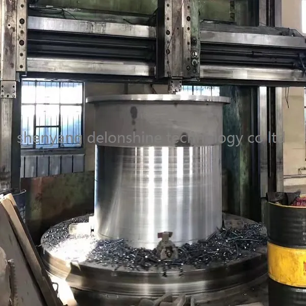 Read More
 -
Jaw Crusher Plates in Hard Rock Quarrying
October 7, 2026A granite quarry asks more of a quarry jaw crusher plate than a river gravel pit does. Rock that is hard, abrasive and blocky puts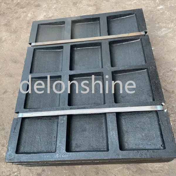 Read More
 -
Jaw Crusher Plate Material Grades: Mn13, Mn18 and Mn22
October 7, 2026Two quotations for the same jaw crusher plate often differ by a wide margin, and the reason is usually the grade written on the dr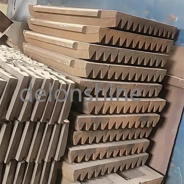 Read More
 -
Jaw Crusher Plate Explained: Fixed Plate versus Swing Plate
October 6, 2026A jaw crusher plate absorbs the first impact of every rock that enters a primary crusher. Two plates work as a pair, one bolted to
Read More

Contact Us
Recommended Products
-
 Vertical Mill Reducer Planetary Gear AssemblyNegotiableMOQ: 2 Combos
 -
High Precision Mining Equipment End Cover Wear Resistant Crusher End CapNegotiableMOQ: 2 Pieces
-
Heavy Duty Mining Equipment Cast HousingNegotiableMOQ: 2 Pieces
-
Mining Parts Concave MantleNegotiableMOQ: 2 Pieces
-
High Strength Cast Steel Crusher Lifting Beam Heavy Load Mining Equipment Spare PartNegotiableMOQ: 2 Pieces
-
OEM Replacement Mining Spare Parts for Stone Crushing PlantNegotiableMOQ: 2 Pieces
-
Cast Steel Ball Mill Head for Mineral ProcessingNegotiableMOQ: 2 Pieces
-
Large Diameter Cast Gear for Ore Grinding MillNegotiableMOQ: 2 Pieces
-
Wear Resistant Mining Spare PartsNegotiableMOQ: 2 Pieces
-
Industrial Wet Dry Ball Mill for Mineral ProcessingNegotiableMOQ: 2 Pieces


-
High Wear Resistant Ball Mill Wear Parts Ball Mill Gear Pinion Liner for Mining Processing PlantNegotiableMOQ: 2 Pieces
-
Heavy Duty Equipment CasingNegotiableMOQ: 2 Pieces
-
Customized Main Shaft for Cone CrusherNegotiableMOQ: 2 Pieces
-
Ball Mill Head With Flange and Bolt HolesNegotiableMOQ: 2 Pieces
-
Heavy Duty Equipment CasingNegotiableMOQ: 2 Pieces


-
Crusher Wear Parts for Mining MachineryNegotiableMOQ: 2 Pieces
-
High Manganese Steel Jaw Crusher Fixed & Swing PlatesNegotiableMOQ: 2 Pieces
-
Cast Steel Safety Toggle Plate for Jaw Crusher Overload ProtectionNegotiableMOQ: 2 Pieces
-
High Manganese Steel Mill LinerNegotiableMOQ: 2 Pieces
-
Main Shaft Steel Sleeve Lock Nut for Cone CrusherNegotiableMOQ: 2 Pieces