
 Business License

Quality Control at Delonshine: Five Inspection Stages
A heavy casting is as good as the checks that were made while it was being made.
Once a mill end cover or a girth gear leaves the works, the evidence of how it was produced travels with it in the form of test coupons, furnace charts and inspection reports.
Shenyang Delonshine Technology Co Ltd built its casting quality control system around five inspection stages, arranged so that a problem is found at the point where it can still be corrected.
This article walks through each stage and explains what the customer receives from it.
1. The Casting Quality Control System at Delonshine in Five Stages
The casting quality control system at the works covers incoming material, mould and pattern preparation, non destructive testing, heat treatment, and final dimensional inspection.
Each stage has a written procedure, a responsible person and a record that is filed against the order number.
The five stages are not independent, and that is deliberate.
A chemistry error found at stage one is corrected in the furnace at modest cost.
The same error found at stage three, after the casting has cooled and the pattern has been consumed, may mean a scrapped pour and a delay measured in weeks.
Early detection is the principle that shapes the whole sequence.
The table below summarises what each stage checks and what the customer receives from it.
| Stage | What is checked | Customer receives |
|---|---|---|
| One | incoming material and melt chemistry | chemical analysis report |
| Two | pattern, mould and core preparation | dimensional check before pouring |
| Three | internal and surface soundness | non destructive test report |
| Four | heat treatment cycle | furnace chart and record |
| Five | final dimensions and markings | dimensional report with photographs |
Customers who audit a supplier usually ask for those five documents, and Delonshine keeps them on file so that a repeat order can be compared with the original one. Parts are shipped through Dalian, Tianjin, Qingdao and Shanghai to customers across 13 export regions, and the plant covers 5,000 to 10,000 square metres with a workforce of between 51 and 100 people.
2. Stage One: Incoming Material Control Before Casting
Stage one begins before any metal is melted, because the quality of a casting is limited by what goes into the furnace.
Scrap, ferroalloys and returned risers are checked for grade and cleanliness, and material with unknown provenance is kept out of the charge.
Incoming material control before casting is the least visible part of the process and the one that prevents most chemistry problems. The works melts in a 20 tonne electric arc furnace supported by induction furnaces of 7 to 10 tonnes, and single castings can reach 100 tonnes.
Chemistry is then confirmed at the furnace.
A sample is taken and analysed before the heat is tapped, so that an adjustment can still be made in the ladle.
Carbon, manganese, silicon, chromium and molybdenum are the elements watched most closely for the wear part grades the works produces.
The table below lists the checks carried out at this stage.
| Check | Method | Timing |
|---|---|---|
| Charge material identity | document and visual inspection | before charging |
| Melt chemistry | spectrometer sample | before tapping |
| Pouring temperature | immersion thermocouple | at the ladle |
| Test coupon casting | poured with the production mould | during pouring |
A coupon poured with the casting is the reason the figures on the certificate describe the metal in the part rather than the metal in the furnace.
That principle runs through the casting quality control system from the first charge to the last inspection.
3. Stage Two: Mould and Pattern Control for Each Casting
Stage two covers the tooling and the sand, and it decides whether the casting will have the wall thickness the drawing assumes.
Pattern and core box dimensions are checked when the tooling is made and rechecked at fixed intervals during production.
Mould and pattern control for each casting protects the customer against a slow drift that would otherwise appear over a batch of parts.
Sand properties matter as much as the pattern.
Compaction, moisture and binder content affect how the mould behaves when the metal arrives.
A mould that is too weak washes at the gate and produces a rough surface, while one that is too hard traps gas and produces blowholes.
The table below shows the checks applied before a mould is closed.
| Item | Check | Frequency |
|---|---|---|
| Pattern dimensions | against the drawing | first article and monthly |
| Core position | clearance and support | every mould |
| Sand compaction | hardness at fixed points | every shift |
| Mould and core assembly | closing gap and bolts | every mould |
| Riser and gating layout | against the pattern record | every mould |
Excess metal at a joint is easy to grind away, while a short pour or a shifted core can scrap the part, so the assembly check is done before the metal is committed.
4. Stage Three: Ultrasonic Flaw Detection Service on Critical Castings
Stage three looks inside the metal once it has cooled, and it is where an ultrasonic flaw detection service earns its place.
Ultrasonic testing sends a high frequency pulse into the casting and reads the echoes that return from internal features.
A void, a shrinkage cavity or a crack reflects the pulse and appears as a signal at a known depth.
Magnetic particle inspection is used alongside it on surfaces that can be magnetised.
The method finds surface and near surface defects that ultrasonic testing may pass over, and the two techniques answer different questions.
For a mining big gear or a mill end cover, the choice of method follows the drawing requirement and the stress the part will see.
The table below compares the methods used at this stage.
| Method | Finds | Typical application |
|---|---|---|
| Ultrasonic testing | internal voids and cracks | thick sections, bores, gear rims |
| Magnetic particle testing | surface and near surface defects | machined faces and fillets |
| Visual inspection | surface condition and marks | every casting |
| Dimensional check | wall thickness and key sizes | every casting |
Findings are written into a report with the location, the size and the acceptance figure applied, and Delonshine Technology issues that report with the delivery documents, with each finding also logged inside the casting quality control system against the heat number.
5. Stage Four: Heat Treatment Record Documentation
Stage four decides the mechanical properties of the part, and heat treatment record documentation is the evidence that the cycle was actually performed as specified.
The furnace chart shows the temperature against time, including the heating rate, the soak period and the cooling method.
A casting with the correct chemistry and the wrong heat treatment will miss its specification, and the chart is the one reliable way to prove which of the two happened.
The cycle itself depends on the grade, and for every heat the heat treatment record documentation is completed before the casting leaves the furnace area.
Carbon and low alloy steel castings are normalised or normalised and tempered.
Manganese steel is supplied in the solution treated condition, and the cooling rate after the soak is controlled rather than left to the air.
The table below lists what the record contains for each grade family.
| Grade family | Typical cycle | Record contents |
|---|---|---|
| Carbon steel | normalise | chart, load number, furnace id |
| Low alloy steel | normalise and temper | chart, soak time, temper temperature |
| Manganese steel | solution treat with controlled cooling | chart, quench start and finish time |
| Heat resistant alloy | solution treat | chart, cooling rate, coupon results |
Each chart is stored against the order and the heat number, which is what makes a traceable claim possible years after delivery.
6. Stage Five: Final Dimensional Control Before a Casting Leaves the Works
Stage five is the last chance to catch a problem before freight is committed, and it covers dimensions, markings and surface condition.
Critical sizes are measured against the drawing, and the results are recorded rather than checked off as acceptable.
Final dimensional control before a casting leaves the works also confirms that machining allowances are even and that no feature has been missed.
Marking is part of this stage.
Heat number, part number and customer reference are stamped or painted so that the casting can be identified after it is unpacked at the mine.
Photographs of the finished part, the crate and the markings complete the record.
The table below lists the checks and the acceptance basis for each.
| Check | Acceptance basis |
|---|---|
| Critical dimensions | drawing tolerance |
| Wall thickness | minimum figure on the drawing |
| Machined surfaces | no defects after final cut |
| Identification marks | heat and part number legible |
| Surface finish of bores | roughness within specification |
Shenyang Delonshine Technology issues the dimensional report together with the packing photographs, so that the customer can compare what was ordered with what was loaded.
The same discipline applies to the ultrasonic flaw detection service, which reports before release rather than after it.
7. How the Five Stages Form One Casting Quality Control System
The five stages work as a set, because each one passes information to the next.
The chemistry from stage one sets the heat treatment cycle at stage four, and the mould record from stage two explains a dimensional result at stage five.
Breaking the chain at any point removes the ability to trace a problem back to its cause.
That tracing ability is what a customer is really buying when they audit a foundry, and it rests on the heat treatment record documentation as much as on the test reports themselves.
A supplier who can produce a chart, a coupon result and a dimensional record for a specific casting is a supplier who understands the process rather than a trader who forwards orders.
It is also the reason the casting quality control system is written down rather than held in the memory of a few experienced hands.
The table below shows how one stage supports the next.
| Stage | Output that feeds the next stage |
|---|---|
| One | chemistry and grade confirmation |
| Two | mould and core assembly record |
| Three | defect report and repair decision |
| Four | furnace chart and coupon results |
| Five | dimensional report and markings |
Delonshine Technology keeps the whole set against the order number, and customers who return for a repeat part receive the same package again.
8. What the Ultrasonic Flaw Detection Service Records Show
A test report is useful when a reader can tell what was examined and what was found.
An ultrasonic flaw detection service report should state the method, the standard applied, the scanning coverage, the equipment used and the acceptance criteria agreed for that part.
Without the coverage figure, a report that says no defects were found says little about the areas that were never scanned.
The findings section is written in figures as well as words.
Each indication is described by its position, its depth and its size, and each one is compared with the acceptance figure.
An indication below the acceptance figure is documented rather than concealed, and a repair, where permitted, is recorded with the welding procedure used.
The table below lists what a complete non destructive test report contains.
| Section | Content |
|---|---|
| Part identification | drawing number and heat number |
| Method | technique, standard and equipment |
| Coverage | areas scanned, expressed as a share of the part |
| Results | indication position, depth and size |
| Disposition | accepted, repaired or rejected |
Read alongside the dimensional report, those figures give a buyer a full picture of the part before it is shipped, and the ultrasonic flaw detection service report stays with the order file afterwards.
9. Frequently Asked Questions about Casting Quality Control
9.1 Who carries out the inspection at each stage?
Each stage is handled by the production team that performs the work and verified by an inspector who does not report to that team. The separation matters, because a moulder checking his own mould is not the same as an inspector checking it against a pattern record. Test coupons are machined and pulled by the laboratory, and the resulting figures are attached to the certificate without adjustment. The customer can ask for a third party inspection on any order, and the works arranges access and holds the casting until the inspection is complete.
9.2 Can a customer witness the ultrasonic flaw detection service?
Yes, and many buyers do. A visit is arranged so that the scanning is carried out while the customer is present, with the acceptance criteria reviewed before the test begins rather than after the results are known. The technician explains each significant indication as it appears on the screen. For an order with several large castings, the inspection can be scheduled over two days, and arranging the visit early is worthwhile since the casting cannot be released for packing until the report is signed.
9.3 How long are heat treatment record documentation kept on file?
Copies of the heat treatment record documentation are held for the life of the part in service, and in practice that means well beyond the delivery date. Each chart is filed against the order number and the heat number, so a customer who needs a copy several years after delivery can request it and receive the original rather than a reconstruction. The same file holds the chemical analysis, the coupon results and the dimensional report. That is the basis on which a repeat order can be matched to the original specification.
9.4 What happens when a casting fails inspection?
The disposition depends on the defect and on the drawing requirement, and an indication below the acceptance figure is recorded while the part continues. A defect above it may be repaired where the specification permits welding, in which case the repair is documented with the procedure and re-inspected before release. A defect outside the permitted repair scope means the casting is scrapped and remade, and the customer is informed with the reason. In most cases the alternative is a delay to the delivery schedule, so the finding is reported as soon as it is confirmed.
Recently Posted
-
Bowl Liner and Mantle: How the Two Cone Crusher Liners Work Together
October 14, 2026A mantle and bowl liner set that is renewed one half at a time usually costs a plant more than a cone liner pair changed as a set,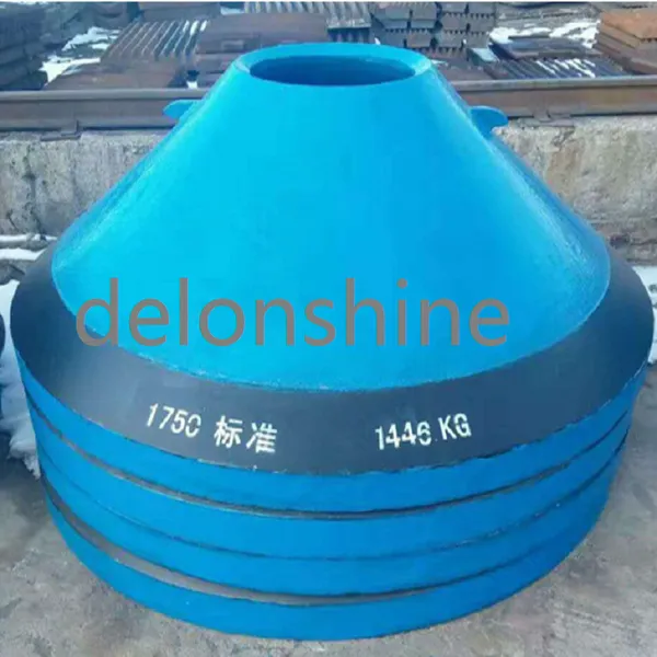 Read More
 -
Bowl Liner Explained: The Stationary Bowl Liner in a Cone Crusher
October 14, 2026An owl liner cone crusher part is the stationary liner that lines the crushing chamber and breaks rock against a moving mantle by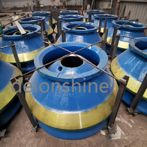 Read More
 -
Bowl Liner and Mantle: How the Two Cone Crusher Liners Work Together
October 13, 2026A mantle and bowl liner set that is renewed one half at a time usually costs a plant more than a cone liner pair changed as a set,
Read More -
Bowl Liner Explained: The Stationary Bowl Liner in a Cone Crusher
October 13, 2026An bowl liner cone crusher part is the stationary liner that lines the crushing chamber and breaks rock against a moving mantle by
Read More

Contact Us
Recommended Products
-
 Vertical Mill Reducer Planetary Gear AssemblyNegotiableMOQ: 2 Combos
 -
High Precision Mining Equipment End Cover Wear Resistant Crusher End CapNegotiableMOQ: 2 Pieces
-
Heavy Duty Mining Equipment Cast HousingNegotiableMOQ: 2 Pieces
-
Mining Parts Concave MantleNegotiableMOQ: 2 Pieces
-
High Strength Cast Steel Crusher Lifting Beam Heavy Load Mining Equipment Spare PartNegotiableMOQ: 2 Pieces
-
OEM Replacement Mining Spare Parts for Stone Crushing PlantNegotiableMOQ: 2 Pieces
-
Cast Steel Ball Mill Head for Mineral ProcessingNegotiableMOQ: 2 Pieces
-
Large Diameter Cast Gear for Ore Grinding MillNegotiableMOQ: 2 Pieces
-
Wear Resistant Mining Spare PartsNegotiableMOQ: 2 Pieces
-
Industrial Wet Dry Ball Mill for Mineral ProcessingNegotiableMOQ: 2 Pieces


-
High Wear Resistant Ball Mill Wear Parts Ball Mill Gear Pinion Liner for Mining Processing PlantNegotiableMOQ: 2 Pieces
-
Heavy Duty Equipment CasingNegotiableMOQ: 2 Pieces
-
Customized Main Shaft for Cone CrusherNegotiableMOQ: 2 Pieces
-
Ball Mill Head With Flange and Bolt HolesNegotiableMOQ: 2 Pieces
-
Heavy Duty Equipment CasingNegotiableMOQ: 2 Pieces


-
Crusher Wear Parts for Mining MachineryNegotiableMOQ: 2 Pieces
-
High Manganese Steel Jaw Crusher Fixed & Swing PlatesNegotiableMOQ: 2 Pieces
-
Cast Steel Safety Toggle Plate for Jaw Crusher Overload ProtectionNegotiableMOQ: 2 Pieces
-
High Manganese Steel Mill LinerNegotiableMOQ: 2 Pieces
-
Main Shaft Steel Sleeve Lock Nut for Cone CrusherNegotiableMOQ: 2 Pieces