
 Business License

Mining Equipment End Cover Dimensions and Bolt Circle Accuracy
A mining equipment end cover is a large casting, and its fit depends on a small number of dimensions rather than on its overall size.
The bolt circle, the bore and the flange face carry the whole assembly relationship.
An error of half a millimetre on a diameter of three metres is invisible to the eye and decisive at assembly.
This article sets out what an end cover bolt circle is, which tolerances matter, and how the dimensions are proven before the casting is shipped.
1. End Cover Bolt Circle: Definition and Why It Governs Fit
An end cover bolt circle is the circle on which the fixing holes are centred, and its diameter is the single figure that most often decides whether a cover can be bolted to its housing.
The full specification of the pattern is made up of four parts: the number of holes, the hole diameter, the diameter of the circle and the angular spacing between adjacent holes.
A cover with the correct hole count and the wrong circle diameter will not assemble, which is why the reference is normally given as a diameter rather than as a distance between holes.
The circle is also the feature that is hardest to verify on a large casting.
A pair of calipers can check the distance between two adjacent holes, and that figure can be correct while the circle is not truly round.
The diameter has to be measured as an averaged figure across several pairs of holes, or by a method that follows the circle itself.
The table below lists the components of a bolt pattern specification.
| Element | Typical value range | How it is stated |
|---|---|---|
| Hole count | 8 to 60 | number |
| Hole diameter | 18 to 70 mm | with fit tolerance |
| Bolt circle diameter | 600 to 8,000 mm | diameter with tolerance |
| Angular spacing | evenly divided | degrees or equal spacing |
| Hole position | measured from a datum | angle from a marked axis |
Shenyang Delonshine Technology Co Ltd records the bolt circle diameter and the measured span between holes on the inspection report for every cover, so that the two figures can be checked against each other.
2. End Cover Dimensional Tolerance: Where It Is Applied
End cover dimensional tolerance is not applied evenly across the part, and treating every dimension the same way raises cost without improving fit.
The tight tolerances belong to the features that locate the cover: the bore, the spigot and the bolt circle.
The outer profile, the rib positions and the casting wall thickness carry wider tolerances that reflect the casting process.
Grouping the features this way lets a foundry concentrate its machining effort where it matters.
It also makes the inspection report readable, because a reader can see at a glance which dimensions were controlled closely and which were not.
The table below sets out a typical tolerance approach for a large cover.
| Feature | Typical tolerance | Reason |
|---|---|---|
| Bore diameter | 0.05 to 0.15 mm | bearing or spigot fit |
| Bolt circle diameter | 0.3 to 0.8 mm | bolt alignment across the joint |
| Hole diameter | 0.2 to 0.4 mm | clearance for the fastener |
| Flange thickness | 0.5 to 1.0 mm | clamping length of the bolt |
| Mating face flatness | 0.05 to 0.15 mm | even contact pressure |
| Overall length | 2 to 5 mm | casting allowance |
A tolerance that appears generous on a drawing can still be tight in absolute terms, and a diameter tolerance of 0.3 millimetres on a 6 metre circle takes planning to hold, which is why end cover dimensional tolerance is agreed before the order is placed.
3. Flange and Mating Face Requirements for an End Cover
The flange is where the cover transfers its load into the housing, and its condition decides whether the bolts stay tight.
A flange face that is not flat contacts the mating surface at a few high points, and the load concentrates there.
Under a fluctuating load the high points yield, the joint relaxes, and the bolts lose their preload even though nobody touched them.
Flatness is therefore specified as a figure over a length rather than as a total value across the whole face.
A limit of 0.1 millimetres per 300 millimetres of length is more meaningful on a large flange than a single overall number.
Surface roughness belongs in the same specification, since a rough face crushes locally and changes the preload after the first tightening.
The table below links a flange characteristic to the effect it has on the joint.
| Characteristic | Effect on the joint |
|---|---|
| Local flatness deviation | uneven contact and bolt relaxation |
| Surface roughness too high | loss of preload after first tightening |
| Face not square to the bore | cover tilts and loads the seal unevenly |
| Bolt hole edge burr | false torque reading during assembly |
| Insufficient flange thickness | face deflection under bolt load |
Those characteristics are checked at the works rather than at the mine, because correcting them on site needs machining equipment that is rarely available, and each of them belongs in the end cover flange specification.
4. Measuring an End Cover Bolt Circle Accurately
Measuring a bolt circle on a casting several metres across needs a method that follows the circle rather than a set of local chords.
A circumference tape wrapped around the circle gives a direct diameter reading and is accurate when the tape is tensioned to its calibration figure.
A span measurement over two fitted pins checks the spacing locally and is useful for confirming a single sector.
A portable coordinate measuring arm or a laser tracker maps every hole position and reports the fitted circle.
The fitting approach matters when an end cover bolt circle is checked on a large cover.
A circle that is slightly oval has no single diameter, and the reported figure depends on which pairs of holes were measured.
A fitting calculation from all hole positions reports the average circle and the deviation of each hole from it, which is the figure an assembly engineer needs.
The table below compares the methods.
| Method | Typical accuracy | Suited application |
|---|---|---|
| Circumference tape | 0.1 to 0.3 mm on diameter | quick confirmation on site or in the shop |
| Span over pins | 0.05 mm | local hole spacing and sector check |
| Coordinate measuring arm | 0.05 to 0.15 mm | full pattern with fitted circle |
| Laser tracker | 0.05 mm over several metres | very large covers and assemblies |
| Inside micrometer | 0.02 mm | bore diameter |
A measurement is useful when the datum is stated, because a position on an end cover bolt circle expressed as an angle means nothing without a reference axis.
5. Bore and Spigot Tolerance in an End Cover
The bore and the spigot position the cover, and their tolerance decides whether the assembly runs true.
A spigot is a raised register that centres one part inside another, and its fit is normally a close clearance rather than an interference.
Too much clearance lets the cover shift under load, while too little prevents assembly when the parts are at different temperatures.
Concentricity links the two features.
The bore and the spigot should share an axis within a stated limit, because a cover that is centred on its outside edge but not on its bore will load the bearing unevenly.
Where a cover carries a bearing seat, concentricity with the mounting register is the dimension that governs running accuracy.
The table below shows the fit types used for locating features.
| Feature pair | Fit type | Typical clearance |
|---|---|---|
| Spigot into housing | close clearance | 0.05 to 0.15 mm |
| Bearing outer race into bore | light interference | 0.02 to 0.06 mm |
| Cover onto flange register | clearance | 0.10 to 0.25 mm |
| Shaft through bore | running clearance | 0.15 to 0.40 mm |
Shenyang Delonshine Technology machines the locating features in one setting where the drawing allows it, because a second setting adds an alignment error that no tolerance on the drawing can remove.
6. Recording End Cover Dimensional Tolerance for Each Cover
A dimensional record turns a casting into a documented product, and for a large cover the record is the chief way a distant buyer can confirm the fit, and it is where end cover dimensional tolerance is proven.
The report lists each controlled dimension, the measured value and the tolerance applied.
Where a dimension could not be measured at the works, the report says so rather than leaving the row blank.
The record also supports assembly planning.
A plant that knows the exact bolt circle diameter can prepare shims, calculate bolt stretch and confirm that the mating holes on the housing will line up.
Discovering a mismatch after the mill is stopped costs far more than a report costs to produce.
The table below lists the dimensions normally recorded for an end cover.
| Dimension | Measured by |
|---|---|
| Bore diameter and roundness | inside micrometer, several positions |
| Bolt circle diameter | tape or coordinate method |
| Hole diameters | plug gauge or internal micrometer |
| Flange flatness | straight edge and feeler gauge |
| Spigot diameter and concentricity | micrometer with a dial indicator |
| Overall height | tape or laser distance meter |
Each row is signed by the inspector who took the reading, which is what gives the document its value in a dispute.
Delonshine keeps a copy of every report against the order number.
7. How End Cover Dimensional Tolerance Decides Assembly
Assembly success is decided by the sum of the tolerances on both parts rather than by either one alone.
The housing has its own bolt circle and its own bore, and the joint works when the two tolerance bands overlap in a way that still allows the fasteners to pass.
A cover held to a tight tolerance fitted to a housing that has worn will still need reaming.
Three outcomes are possible at assembly.
Where the clearance is sufficient, the bolts pass and the joint closes with normal effort.
Where the clearance is marginal, the bolts need drifting into place and the joint takes longer than planned.
Where the clearance is negative, the holes must be reamed oversize, which changes the fastener size and often requires an engineering decision on site.
The table below relates the combined condition to the likely assembly result.
| Combined condition | Likely result |
|---|---|
| Tolerance bands overlap with clearance | bolts pass freely |
| Bands just touch | drifting needed, slow assembly |
| Bands overlap with interference | reaming required |
| Housing circle oval from wear | local reaming or a new housing |
| Flange face not flat | bolt relaxation after tightening |
A buyer can avoid most of those outcomes by supplying the measured dimensions of the housing with the enquiry, and Delonshine Technology asks for them where the machine is old.
8. End Cover Flange Specification for Flatness, Fasteners and Torque
The end cover flange specification ties the dimensions of the casting to the fasteners that will be used.
Bolt size, grade and the tightening method are chosen together with the flange thickness, because a thin flange deflects and loses preload.
The specification should also state the torque figure and whether the bolts are to be tightened by torque or by stretch.
Fastener grade matters more on a large joint than on a small one.
A high strength bolt tightened to a low torque wastes its capacity, while a standard bolt tightened to a high figure may yield during service.
Washers and the condition of the seating face influence how much of the applied torque reaches the bolt as preload.
The table below lists what a complete end cover flange specification contains.
| Item | Content |
|---|---|
| Flange thickness | nominal with tolerance |
| Bolt size and grade | diameter, pitch and strength class |
| Hole diameter and fit | clearance or fitted bolt |
| Torque figure | value and lubrication condition assumed |
| Flatness and roughness | limits over a stated length |
| Sealing method | gasket type or sealant |
A specification that leaves the lubrication condition unstated gives a torque figure that cannot be reproduced, since a dry thread and a lubricated thread reach different preloads at the same wrench setting, and that omission is the most common gap in an end cover flange specification.
9. Frequently Asked Questions about End Cover Dimensions
9.1 What tolerance should be specified for an end cover bolt circle?
A figure between 0.3 and 0.8 millimetres on the circle diameter suits most large covers, and the choice depends on the clearance available in the housing. A joint with generous hole clearance tolerates the wider figure, while a fitted bolt arrangement needs the tighter one. The figure should be stated as a diameter with a plus and minus band rather than as a single limit. Supplying the measured housing dimensions with the enquiry lets the supplier confirm that the chosen band will actually assemble.
9.2 How is an end cover dimensional tolerance verified before shipping?
Each controlled dimension is measured at the works and entered into a report with the value and the tolerance band. Bore and spigot sizes are taken with a micrometer at several positions to capture roundness as well as diameter. The bolt circle is confirmed by a circumference tape or a coordinate method, and the flange face is checked with a straight edge and a feeler gauge. The report is signed by the inspector and issued with the shipment rather than held on file, so that the buyer can compare each figure with the end cover dimensional tolerance that was ordered.
9.3 Can bolt holes be reamed on site if the cover does not fit?
They can, and it is a common solution on older machines, but the decision has consequences. Reaming the holes oversize requires larger fasteners or fitted bolts, and the change has to be recorded so that the next cover is ordered to suit. Portable line boring equipment can handle the work if the housing is accessible and the alignment is controlled. It is a repair rather than a correction, and it is better avoided by measuring the housing before the cover is ordered and by agreeing the end cover flange specification in writing.
9.4 What should an end cover flange specification state about fasteners?
It should give the bolt size, the grade and the tightening method together, because the three work as a set. Under-tightening a high strength bolt and over-tightening a standard one are both common faults, and the specification is where they are prevented. The lubrication condition assumed for the torque figure belongs on the same line, since a dry thread and a lubricated one reach different preloads at the same wrench setting. Washers or hardened seats are named where the flange face is not machined, and the hole fit is stated as clearance or fitted.
Recently Posted
-
Digital Measurement in Mining Big Gear Production
September 18, 2026A girth gear several metres in diameter cannot be carried to a measuring machine, so the measuring machine has to travel to the ge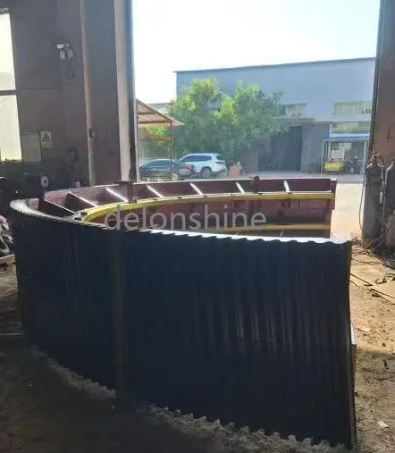 Read More
 -
Mining Big Gear Service in Hot and Dusty Conditions
September 18, 2026A mine gear in hot climate conditions faces two enemies at the same time, and each one makes the other worse. Heat thins the lubri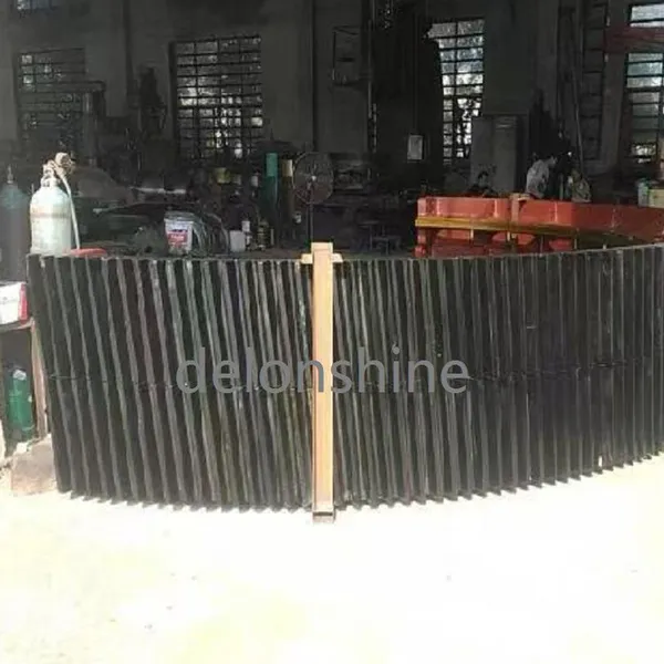 Read More
 -
Hardness versus Toughness in Ball Mill Wear Parts
September 17, 2026Two properties decide how long a wear part lasts, and they move in opposite directions. Wear part hardness and toughness sit at ei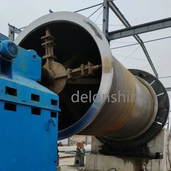 Read More
 -
Mining Replacement Parts versus OEM Parts: What Really Differs
September 17, 2026A maintenance engineer comparing mining replacement parts with original equipment parts is usually asking one question: will the c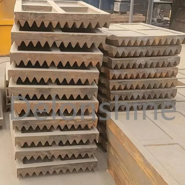 Read More

Contact Us
Recommended Products
-
 Vertical Mill Reducer Planetary Gear AssemblyNegotiableMOQ: 2 Combos
 -
High Precision Mining Equipment End Cover Wear Resistant Crusher End CapNegotiableMOQ: 2 Pieces
-
Heavy Duty Mining Equipment Cast HousingNegotiableMOQ: 2 Pieces
-
Mining Parts Concave MantleNegotiableMOQ: 2 Pieces
-
High Strength Cast Steel Crusher Lifting Beam Heavy Load Mining Equipment Spare PartNegotiableMOQ: 2 Pieces
-
OEM Replacement Mining Spare Parts for Stone Crushing PlantNegotiableMOQ: 2 Pieces
-
Cast Steel Ball Mill Head for Mineral ProcessingNegotiableMOQ: 2 Pieces
-
Large Diameter Cast Gear for Ore Grinding MillNegotiableMOQ: 2 Pieces
-
Wear Resistant Mining Spare PartsNegotiableMOQ: 2 Pieces
-
Industrial Wet Dry Ball Mill for Mineral ProcessingNegotiableMOQ: 2 Pieces


-
High Wear Resistant Ball Mill Wear Parts Ball Mill Gear Pinion Liner for Mining Processing PlantNegotiableMOQ: 2 Pieces
-
Heavy Duty Equipment CasingNegotiableMOQ: 2 Pieces
-
Customized Main Shaft for Cone CrusherNegotiableMOQ: 2 Pieces
-
Ball Mill Head With Flange and Bolt HolesNegotiableMOQ: 2 Pieces
-
Heavy Duty Equipment CasingNegotiableMOQ: 2 Pieces


-
Crusher Wear Parts for Mining MachineryNegotiableMOQ: 2 Pieces
-
High Manganese Steel Jaw Crusher Fixed & Swing PlatesNegotiableMOQ: 2 Pieces
-
Cast Steel Safety Toggle Plate for Jaw Crusher Overload ProtectionNegotiableMOQ: 2 Pieces
-
High Manganese Steel Mill LinerNegotiableMOQ: 2 Pieces
-
Main Shaft Steel Sleeve Lock Nut for Cone CrusherNegotiableMOQ: 2 Pieces